Contents [show]
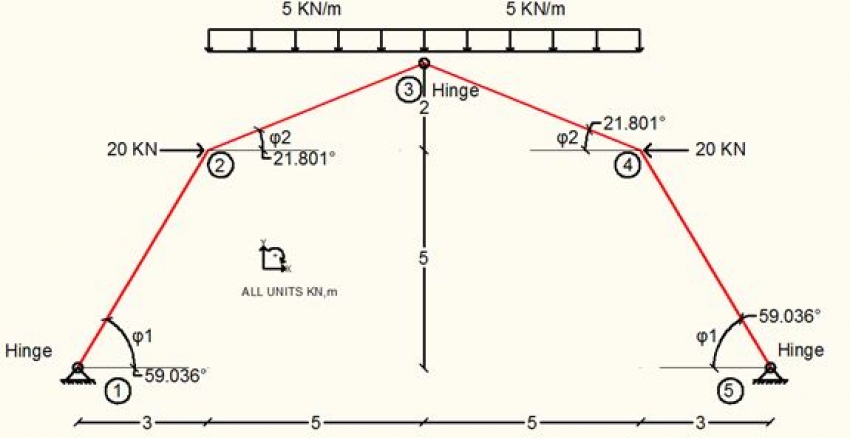
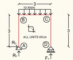
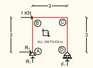
Calculate the member diagrams for Axial Force N, Shear Force S and bending Moment M for the following frame.
Solution
The frame is symmetrical in shape, loading and constraints. So we can work on the left half side.
At point 3 there is no moment because it is a hinge.

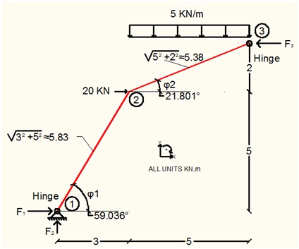
At point 1
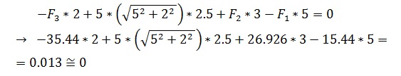
Verification. Equilibrium of Moments at Point 2.
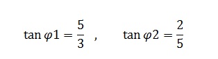
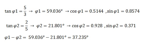
The trigonometrical numbers for angles ?1, ?2 (units degrees) are
The equilibrium of the part 1J – 1S (where the upper script J means Joint and S means Section) gives:

Local Axis x':

Loxal Axis y':

Equilibrium of Moments at Point 1:

From the equilibrium of the part 1S – 2J

Local Axis x':
Loxal Axis y':
Equilibrium of forces at Point 2:

Local Axis x':
Loxal Axis y':
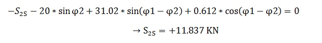
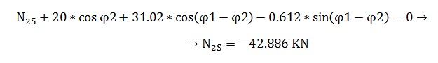
Equilibrium of Moments at Point 2:

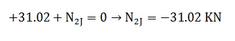
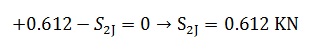
Equilibrium of forces of the part 2S – 3J

Local Axis x':

Loxal Axis y':

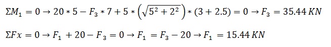
Equilibrium of Moments at Joint 3:

With the above values we make the diagrams for the Axial Force N, Shear Force S and Bending Moment at the members of the left part 1-2-3. Because of symmetry we can have diagrams for the right part 3-4-5. Diagrams for Axial Force and Moment are symmetric and diagram for Shear is antisymmetric.


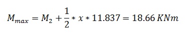
The Shear diagram takes zero value at distance x from Joint 2

This is where Moment has max value
Selected Topics
Want to read more like this?

Calculation Example - Calculate the member diagrams.
Jan, 25, 2017 | EducationCalculate the member diagrams for the point load P for the pinned beam at two ends. Solut...

Calculation Example - Calculate the Axial Forces on the Truss Members
Jan, 20, 2016 | EducationFind the axial forces of the members 2-3, 3-9 of the truss for the given external loads. ...

Calculation Example - Calculate the member diagrams for the beam
Feb, 16, 2016 | EducationCalculate the member diagrams for Axial Force N, Shear Force Q and bending Moment M for the followin...

Calculation Example - Calculate the member diagrams.
Aug, 17, 2016 | EducationCalculate the member diagrams for the uniform loading q for the pinned beam at two ends. So...

Calculation Example - Calculate the Axial Forces of the Truss Members.
Aug, 21, 2017 | EducationFind the axial forces of the members 2-3, 9-3 of the truss for the given loads. Soluti...

Calculation Example – Determine the shear force and moment.
May, 03, 2017 | EducationDetermine the shear force and moment acting at a section passing through point C on the beam....

Calculation Example – Beam with inner hinge (Part B). Calculate the member diagrams.
Mar, 17, 2016 | EducationCalculate the member diagrams. Solution We have already calculated the external beam rea...
Calculation Example – Frame analysis – Uniform Load
May, 09, 2016 | EducationCalculate the reactions and member forces. Solution We calculate the reactions. ...
Calculation Example – Frame analysis.
Apr, 13, 2016 | EducationCalculate the reactions and member forces. Solution We calculate the reactions. Section 1 0...
Trending

Overhanging beam: shear force and bending moment calculation
Truss deflection using the unit load method
Structural stability

Calculation Example – Plastic Neutral Axis.
Nominal flexural strength of a reinforced concrete beam

Calculation Example – Beam with inner hinge (Part A). Find the Reactions
