An engineering point of view for the Tacoma Narrows Bridge collapse

Contents [show]
Introduction
An iconic civil structure is a bridge. The desire for humans to go from place to place without becoming wet goes back as far as recorded history. Yet for so long, there was just one factor that bridge builders had to deal with: gravity. How can we hold up the structure itself, as well as all the people and vehicles that may cross, against the force of gravity dragging them downward, was the fundamental question of bridge design. Furthermore, given that the public funds the majority of bridge construction, how can we do it economically and at the lowest cost to the general populace? As a result, bridge designs have changed over time due to improvements in building materials and structural engineering knowledge, resulting in lighter and more efficient configurations, one of those shapes being the suspension bridge.
The name "suspension bridge" mainly refers to a structure that consists mostly of a deck, two towers, two main cables, and connection rods that suspend the deck. Suspension bridges' main benefit is their ability to cover vast distances with just two towers, using less material and, more crucially, less money. Suspension bridges are known for their recognizable slim and graceful form thanks to the benefit of being able to cross large distances with minimal material. However, the same lack of material affects the rigidity and stiffness of the construction. Whereas formerly, bridges were usually sufficiently strong that gravity was the only load that needed to be taken into account, a new force, the wind, began to influence their designs.
The Tacoma Narrows Bridge
A twin suspension bridge, that spanned the Tacoma Narrows strait and was constructed in 1940, is historically known as the Tacoma Narrows Bridge (Figure 1). It was referred to as a "narrow bridge" due to its extraordinarily long length. Aeroelastic flutter caused it to collapse four months after its construction. Since then, this failure has gained popularity attracting the attention of civil engineers, physicists, and mathematicians. The latter is obvious by the numerous case studies that cover the suspension cable bridge collapse phenomenon.
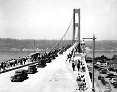
On July 1st, 1940, the construction of Tacoma Narrows Bridge was completed and it was opened to traffic. It was the first bridge of this type (cable suspension) and the first to incorporate a series of plate girders to support the roadbed. With a center span of 2800 feet and two side spans of 1100 feet each, it was also the third-largest suspension bridge in the world at the time.
The bridge’s east side had a long reinforced concrete structure measuring 210 feet, while the west side had a continuous steel girder measuring 450 feet. It featured two 26-foot cable anchorages along with two 5-foot walkways and two 8-foot-deep stiffening girders. The suspended cable anchorages, to which the cables were attached, were made of 20,000 cubic yards of concrete, 6 lakh pounds of structural steel, and 2.7 lakh pounds of reinforcing steel. In 1940, a staggering $6 million was thought to have been spent in total on construction. This is almost $1 billion, adjusted for inflation, for something that endured for four months and seven days. However, this remains a great engineering feature for civil engineers worldwide.
The Incident
The Tacoma bridge was discovered to dangerously buckle and sway along its length under wind loading, not long after it was built. The engineers were concerned about the stability of the bridge in case of strong winds because it was noticeably oscillating even with the normal wind conditions. This alarmed many scientists and engineers, to experimentally test the structural stability of the bridge when subjected to wind loading in a wind tunnel.
On the day of the Tacoma Narrows Bridge collapse (Figure 2), the wind’s velocity was 19m/s, i.e. about 70kmph. Nine distinct parts of the center were torsionally vibrating at a frequency of 36cpm (cycles/min). During an hour, the motion had altered from rhythmically rising and falling to a two-wave twisting as the torsional vibration amplitude increased. Despite all of these movements, the bridge's middle section stayed motionless as its two other parts twisted in opposition to one another.
The bridge experienced 14 tremors per minute and was clearly torn in two. The collapse of a cable band connecting to the middle of the diagonal ties caused this severe twisting to occur. The towers carrying them were dragged in the direction of them as a result of alternate span members sagging and hogging. Before the entire bridge collapsed into the river, clear and noticeable cracks also appeared.

Although there were no casualties, the incident was still a shocking engineering disaster. The University of Washington's Prof. F.B. Farquharson was in charge of carrying out the experiments to comprehend the oscillations. The professor and his crew captured the movement of the bridge on camera on this day, and we can see this footage online today on YouTube.
The following videos present the collapse of the bridge:
Investigations after the collapse
For the wind tunnel tests and to clearly comprehend the reason for collapse (Figure 3), a three-dimensional model at a 1:200 scale was developed. The investigations gave rise to a new theory: wind-induced oscillations because the cause that led to the collapse of the Tacoma Narrows Bridge was not a brand-new problem; rather, it was an unidentified issue.
Increased stiffness due to wind action can be demonstrated through a variety of design techniques, such as increasing the dead load, implementing dampers, stiffening trusses, or using guy cables. These factors, however, were not initially taken into account and were added to forensics much later.
The bridge's shape was unstable from an aerodynamic perspective in the transverse direction. The vertical girders of the H-shape enabled flow separation, which resulted in the formation of vortices that matched the oscillation's phase. The energy produced by these vortices was sufficient to move the girders from their place.

Engineering behind the collapse
The aeroelastic flutter was the primary cause of the Tacoma Narrows Bridge collapse. Trusses are used in typical bridge design to allow wind to move through the structure. In contrast, it was compelled to pass above and below the Tacoma Narrows Bridge, which caused flow separation. As the flow passes through an object, such flow separation in the presence of an object might result in the construction of a Kármán vortex street.
The Strouhal frequency (fs) is the vortex frequency in the Kármán vortex street and is calculated following the equation:

where S is the Strouhal number, D is the characteristic length, and U is flow velocity. For example, for a Reynolds number greater than 1000, S is 0.21. In the case of the Tacoma Bridge, D was 8 ft. and S was 0.20.

Insights
A new bridge was redesigned in 1950 using the lessons learnt from the Tacoma Narrows Bridge disaster. The recently constructed bridge included open (triangular) trusses, strengthening struts, and openings in the roadbeds that enabled the wind to freely pass through. The twisting that emerged in the new bridge was significantly less severe than it was in the old design.
The Whitestone Bridge in the US was fortified after the Tacoma Narrows Bridge catastrophe by installing trusses and openings below road decks to reduce vibrations, and it has been discovered that these are still functional today. After this catastrophe, the concept of applying dynamic and modal analysis for bridge design gained significantly more momentum.
Many structural engineers employ intricate analytical techniques to determine stresses, deflections, etc. In fact, the Finite element analysis (FEA), that was finally developed as a general tool for designing civil engineering structures, was addressed as a result of several failures; among them was the collapse of the Tacoma Narrows Bridge.
Engineering simulation now plays a significant role in the testing phase of bridge design. Engineers can prevent disasters, like the collapse of the Tacoma Narrows Bridge, by simulating wind loads using CFD and examining stresses and the structural behavior of bridges with FEA.
The following videos capture the introduction of wind loads on structures with Computational Fluid Dynamics (CFD) simulations:
Sources
Selected Topics
Want to read more like this?

Types of bridges
Jun, 01, 2023 | EducationArch Bridge An arch bridge is a type of bridge that uses a curved, semi-circular structure, kno...

Tacoma Narrow Bridge Collapse
Jan, 01, 2019 | EducationThe Tacoma Narrows Bridge became famous for its dramatic wind-induced structural collapse in 1940, I...

The most famous bridges of the world
Aug, 26, 2015 | NewsThere are so many bridges in the world in different styles, like old stone bridges or steely, footbr...

World's most frightening bridges to cross: Part 1
Mar, 20, 2020 | NewsBridges are structures that enable crossings over physical barriers including rivers, valleys and c...
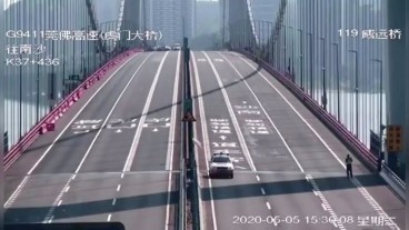
Concrete “waves” formed at Humen Bridge in China
May, 05, 2020 | NewsOn Tuesday May 5th, the top of the Humen Bridge, Southern China’s suspension bridge, oscillated lik...
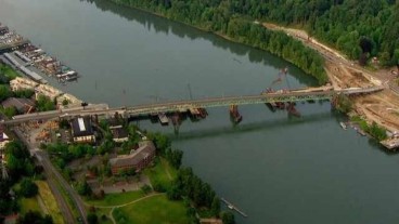
Historic Oregon Bridge For Sale
Aug, 15, 2014 | NewsIf anyone is in the market for purchasing an old bridge here is your chance. Multnomah county i...

Interesting bridges around the world
Mar, 20, 2017 | NewsEach one of them is unique in its own way! 1. Sidu River bridge,...

10 of the longest floating bridges worldwide
Apr, 24, 2024 | NewsConsidered feats of modern engineering, floating bridges play a crucial role in areas where underwa...

Six Injured in Brent Spence Bridge Crash
Aug, 05, 2014 | NewsSix people were injured this weekend in Cincinnati, Ohio when a car fell off the southbound deck of...
External Resources
Trending

Diaphragms
Truss deflection using the unit load method
Structural stability
Nominal flexural strength of a reinforced concrete beam

Calculation Example – Plastic Neutral Axis.

Overhanging beam: shear force and bending moment calculation
Time History Analysis: process and advantages
