CADS Composite Beam Designer
CADS Composite Beam Designer is a program for use in the structural design or checking of Composite Beams CADS Composite Beam prepares calculations for strength, stability and stiffness.
Download DocumentationCADS Composite Beam Designer is a program for use in the structural design or checking of Composite Beams CADS Composite Beam prepares calculations for strength, stability and stiffness. This is in accordance with BS5950 Part 3: Section 3.1:1990 `Code of practice for design of simple and continuous composite beams´. CADS Composite Beam Designer designs composite beams at final (composite) stage, and at construction (non-composite) stage. It can be operated in either Check or Auto-Design mode, in which the software automatically selects adequate section(s) according to the users´ preference for section type, and selection criteria such as minimum weight, minimum depth or width.
'Auto-Design' and 'Check' modes - users can choose how to use CADS Composite Beam Designer. The choices are:
- Check Mode - Where the steel section is specified by the user and the program checks the adequacy of the section for the given materials and load.
- Auto-Design Mode - Where the program automatically selects the passed section(s) type of sections (including UB, UC RSJ, IPE, IPN etc.), according to the users´ preference for minimum depth or width.
Design Parameters - users may control floor vibration by specifying acceptable deflection limits and the natural frequency limit of the beam. Pre-camber can also be accommodated. Props may be used at the construction stage to reduce deflections and prevent the capacity of the steel beam from being exceeded before the concrete gains sufficient strength. The software omits all construction stage checks for propped beams.
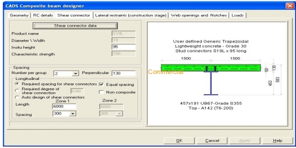
Shear Connections - composite action between the steel beam and the concrete slab is developed by the use of appropriately designed and detailed shear connectors. Shear connectors can be selected from a library of commercial products.
Final stage composite beams are considered as continuously restrained. Point and distributed restraints applicable for the construction stage checks may be specified by the user at the top, bottom, both or centre of the beam.
Web Openings & Notches - rectangular or circular openings (including stiffeners), necessary to accommodate services, etc. may be defined in the webs of I-sections and hollow sections. End notches can also be specified.
Loads - uniform, point and distributed dead or imposed loads may be specified for construction and final stages. A tick box adds the self weight of steel beam as a UDL. Beam loadings can also be given in terms of area loads by ticking the floor load option.
On-Screen Reports - calculation results are displayed in a user friendly and self-explanatory explorer tree type layout and are offered in several layers of detail, from summary to in-depth calculation results.
Printed Reports - there are two printout options available, detailed and single page summary. Both can be previewed on-screen prior to printing and customised with the user´s company details and logo.
| Category | Structural systems , Beams , Structure types , Steel structures |
| Licence Type | Commercial |
| Developer | Computer and Design Services Ltd |
| Developer Website | http://www.cads.co.uk/ |
| Developer Email | [email protected] |
Recommended Software

SDC for Ansys

SDC for Simcenter 3D

SDC for Femap


